All posts by kndele_admin

Common Faults in Three-Phase Voltage Current Protectors and How to Fix Them

Introduction

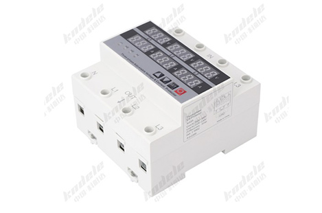
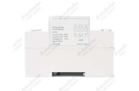
Three-phase voltage current protectors are widely used in industrial power systems to safeguard motors, pumps, and electrical equipment. While they are generally reliable, like any electrical device, they can develop faults due to incorrect installation, unstable power conditions, or component aging.

False Tripping (Frequent Unnecessary Shutdowns)

Problem:

The protector disconnects power even when the system appears normal.

Possible Causes:

Voltage or current threshold set too low

Temporary power fluctuations in the grid

Loose wiring connections

Sensitive delay settings

How to Fix:

Adjust voltage/current protection limits according to equipment ratings

Increase delay time settings to avoid reacting to short spikes

Check and tighten all wiring terminals

Use stable power supply or add surge protection if needed

No Output / Device Does Not Start

Problem:

The protector does not allow power output even under normal conditions.

Possible Causes:

Incorrect wiring of phase or neutral lines

Phase sequence error

Input voltage outside working range

Internal relay failure

How to Fix:

Recheck wiring according to the installation diagram

Confirm correct phase sequence (L1, L2, L3)

Measure input voltage to ensure it is within rated range

Replace internal relay if it is damaged

Overvoltage or Undervoltage Alarm Triggered Constantly

Problem:

The device continuously detects voltage abnormality.

Possible Causes:

Unstable grid voltage

Incorrect voltage calibration settings

Faulty voltage sensing circuit

How to Fix:

Verify actual voltage with a multimeter

Recalibrate voltage settings

Use voltage stabilizer in unstable power environments

Replace sensing module if faulty

Phase Loss Alarm Even When Power Is Normal

Problem:

Protector reports phase loss but all phases are present.

Possible Causes:

Loose phase wiring

Poor contact at terminals

Damaged input line

Internal detection circuit fault

How to Fix:

Inspect and tighten all phase connections

Replace damaged cables

Check terminal oxidation or burning marks

Replace detection module if needed

Overcurrent Protection Triggered Too Easily

Problem:

Device disconnects under normal load conditions.

Possible Causes:

Current setting too low

Motor startup surge not properly configured

Incorrect CT (current transformer) ratio setting

How to Fix:

Increase overcurrent threshold based on motor rated current

Adjust startup delay time

Verify correct CT ratio settings

Display Error or No Display

Problem:

Screen shows abnormal characters or no display at all.

Possible Causes:

Power supply issue

Internal circuit damage

Loose display connection

How to Fix:

Check control power supply voltage

Reconnect display wiring

Replace display module if damaged

Relay Not Switching

Problem:

Protector detects normal conditions but does not switch ON/OFF.

Possible Causes:

Relay contact wear

Control signal failure

Internal circuit malfunction

How to Fix:

Test relay manually if possible

Replace relay module

Inspect control board for damage

Incorrect Parameter Settings

Problem:

Device behaves unpredictably due to improper setup.

Possible Causes:

Factory settings not adjusted

Wrong voltage/current parameters

Mismatch with actual system load

How to Fix:

Reset to factory settings

Reconfigure parameters according to equipment nameplate

Follow manufacturer’s setup guide carefully

Preventive Maintenance Tips

To reduce faults and extend device life:

Regularly check wiring connections

Ensure proper ventilation in control cabinets

Avoid operating beyond rated load

Periodically verify voltage and current accuracy

Perform routine inspections of terminals and relays

Conclusion

Most faults in three-phase voltage current protectors are not caused by device failure but by incorrect settings, wiring issues, or unstable power conditions. With proper installation, regular inspection, and correct parameter configuration, these devices can operate reliably for long periods.

Understanding these common issues helps ensure stable protection for motors and electrical systems while minimizing downtime and maintenance costs.

FAQ

1. Why does a three-phase voltage current protector trip frequently?

Frequent tripping is usually caused by incorrect parameter settings, unstable power supply, or motor startup current being too high. Adjusting delay time and protection thresholds often solves the issue.

2. What should I do if the protector shows no output?

First check wiring connections and phase sequence. If wiring is correct, verify that input voltage is within the rated range. A faulty relay inside the device may also need replacement.

3. Why does the device alarm for overvoltage or undervoltage when power is normal?

This may happen due to inaccurate voltage settings or unstable grid conditions. Recheck actual voltage with a multimeter and recalibrate the device parameters if needed.

4. How do I fix a false phase loss alarm?

Inspect all phase wiring for looseness or poor contact. If wiring is correct, the issue may come from a damaged detection circuit inside the protector.

5. Why is overcurrent protection triggered too easily?

The current limit may be set too low or not aligned with the motor’s rated current. Adjust the setting and ensure correct CT (current transformer) ratio if used.
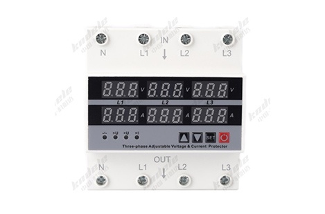
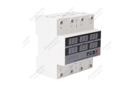
How Voltage Current Protectors Reduce Equipment Failure and Maintenance Costs

Introduction

In modern industrial and commercial power systems, equipment reliability directly affects productivity and operating costs. Motors, pumps, HVAC systems, and production machinery all depend on stable electrical conditions. However, voltage fluctuations, overloads, and phase faults are common in real-world power networks.

A voltage current protector helps solve this problem by continuously monitoring electrical parameters and preventing abnormal conditions from damaging equipment. This not only reduces failures but also significantly lowers maintenance costs over time.

The Hidden Cost of Electrical Failures

When electrical protection is insufficient, equipment is exposed to risks such as:

Motor burnout

Control system damage

Frequent circuit breaker trips

Unexpected production downtime

Emergency repair expenses

These issues often lead to:

High replacement costs

Loss of productivity

Increased labor and service fees

Shortened equipment lifespan

Even minor electrical instability can accumulate into major operational losses.

What Is a Voltage Current Protector?

A voltage current protector is a safety device designed to monitor:

Voltage levels (overvoltage / undervoltage)

Current load (overcurrent / overload)

Phase sequence and phase loss

Power supply stability

When abnormal conditions are detected, it immediately disconnects the load to prevent damage.

How It Reduces Equipment Failure

Prevents Overload Damage

Overload is one of the most common causes of equipment failure.

The protector detects excessive current and shuts down the system before:

Motor windings overheat

Mechanical components are stressed

Insulation damage occurs

This early intervention significantly reduces breakdown rates.

Protects Against Voltage Instability

Voltage fluctuations can silently damage sensitive equipment.

The device reacts to:

Overvoltage (damages insulation and electronics)

Undervoltage (causes inefficient operation and overheating)

By cutting off unstable power, it prevents long-term degradation.

Eliminates Phase-Related Failures

In three-phase systems, phase issues are critical risks.

The protector identifies:

Phase loss

Phase imbalance

Phase reversal

These faults can quickly destroy motors if not detected early.

Reduces Electrical Stress on Equipment

Frequent electrical stress leads to cumulative wear and tear.

By ensuring stable operating conditions, the protector helps:

Extend motor lifespan

Reduce component fatigue

Maintain consistent performance

How It Reduces Maintenance Costs

Fewer Emergency Repairs

Most maintenance costs come from unexpected breakdowns. By preventing faults before they escalate, voltage current protectors reduce emergency repair frequency.

Lower Replacement Frequency

Protecting motors and electrical equipment from damage means fewer replacements of:

Motors

Contactors

Control modules

Wiring components

This directly reduces capital expenditure.

Reduced Downtime Costs

Production downtime is often more expensive than repair itself.

With early fault detection:

Systems shut down safely

Damage is avoided

Restart is faster and more controlled

This improves overall operational efficiency.

Extended Equipment Lifespan

Stable electrical conditions reduce stress on all system components, resulting in:

Longer service intervals

Slower wear and aging

Better return on investment (ROI)

Industrial Applications

Voltage current protectors are widely used in:

Manufacturing equipment

HVAC systems

Water pump stations

Conveyor systems

Agricultural machinery

Energy storage and solar systems

In all these environments, equipment reliability is critical to cost control.

Long-Term Value for Businesses

Investing in a voltage current protector is not just about protection—it is a cost-saving strategy.

Long-term benefits include:

Lower maintenance budgets

Reduced equipment failure rates

Improved system stability

Higher production uptime

Better asset utilization

Conclusion

Voltage current protectors play a crucial role in modern electrical systems by preventing abnormal voltage and current conditions from damaging equipment. Their ability to detect faults early and disconnect power instantly helps businesses significantly reduce equipment failures and long-term maintenance costs.

In industrial operations where downtime and repair costs can be substantial, these devices provide a simple yet highly effective way to improve reliability and protect long-term investments.

FAQ

1. How do voltage current protectors reduce equipment failure?

They continuously monitor voltage and current conditions. When abnormalities such as overvoltage, undervoltage, or overload occur, the device disconnects the power supply before the equipment is damaged, preventing failures from escalating.

2. What types of equipment benefit most from voltage current protection?

They are especially effective for:

Electric motors

Water pumps

HVAC systems

Industrial machinery

Conveyor systems

Electrical distribution panels

3. Can voltage current protectors really reduce maintenance costs?

Yes. By preventing electrical faults early, they reduce the need for emergency repairs, component replacements, and unplanned maintenance, all of which are major cost drivers in industrial systems.

4. How does it help extend equipment lifespan?

By keeping voltage and current within safe operating limits, the protector reduces electrical and thermal stress on components. This slows down wear and tear, allowing equipment to operate longer with fewer failures.

5. What kinds of failures can it prevent?

It helps prevent:

Motor burnout

Overheating damage

Phase loss failures

Control system breakdowns

Insulation damage caused by voltage spikes

6. Does it reduce production downtime?

Yes. Since it can quickly detect and isolate faults, it prevents severe equipment damage that would otherwise cause long repair downtime. It also allows faster recovery once conditions normalize.

How Voltage Current Protectors Improve Safety in Motor Control Systems

Introduction

Motor control systems are the backbone of modern industrial and commercial operations. From water pumps and HVAC units to production machinery, electric motors run critical processes every day. However, motors are highly sensitive to unstable electrical conditions such as voltage fluctuations, phase loss, and overload.

A voltage current protector plays a key role in ensuring these systems operate safely, efficiently, and with minimal downtime.

Why Motor Protection Is Necessary

Electric motors are designed to operate within specific electrical parameters. When these limits are exceeded, serious problems can occur:

Overheating of windings

Insulation breakdown

Reduced motor lifespan

Sudden system shutdowns

Complete motor burnout

These failures not only damage equipment but can also interrupt production and increase maintenance costs significantly.

What Is a Voltage Current Protector?

A voltage current protector is an electrical safety device that continuously monitors:

Voltage levels (overvoltage / undervoltage)

Current load conditions (overcurrent / overload)

Phase sequence and phase loss

Power supply stability

When abnormal conditions are detected, it automatically disconnects the motor from the power supply to prevent damage.

How It Improves Safety in Motor Control Systems

Prevents Overload Damage

Motors often face overload during startup or heavy load conditions. The protector detects excessive current and disconnects power before the motor overheats.

This prevents:

Coil burnout

Mechanical stress

Long-term performance degradation

Protects Against Voltage Fluctuations

Unstable voltage is one of the most common causes of motor failure.

The protector reacts to:

Overvoltage (which can damage insulation)

Undervoltage (which causes insufficient torque and overheating)

By isolating the motor during abnormal voltage conditions, it ensures stable operation.

Detects Phase Loss and Phase Imbalance

In three-phase systems, losing one phase can severely damage a motor.

A voltage current protector immediately detects:

Phase loss

Phase imbalance

Phase reversal

Once detected, it shuts down the motor before damage occurs

Reduces Electrical Fault Risks

Electrical faults such as short circuits or sudden surges can be dangerous.

The protector acts as a first line of defense by:

Interrupting power instantly

Preventing cascading system failures

Reducing fire risk caused by overheating

Extends Motor Lifespan

By ensuring motors always operate within safe electrical conditions, the device significantly reduces wear and tear.

Benefits include:

Longer service life

Lower maintenance frequency

Improved operational efficiency

Enables Automatic Protection and Recovery

Modern voltage current protectors often include automatic reset functions.

This means:

The system shuts down during faults

It restarts automatically once conditions normalize (or manually, depending on configuration)

This reduces downtime and improves production continuity.

Where It Is Commonly Used

Voltage current protectors are widely applied in:

Industrial motor drive systems

Water pumping stations

Air conditioning and HVAC systems

Conveyor and automation equipment

Manufacturing production lines

Agricultural irrigation systems

Key Advantages in Motor Control Systems

Using a voltage current protector provides:

Real-time electrical monitoring

Faster fault response than manual protection

Reduced equipment failure rates

Improved system reliability

Lower operational costs

Conclusion

Voltage current protectors are essential safety components in modern motor control systems. By continuously monitoring electrical conditions and responding instantly to abnormalities, they prevent costly motor damage and ensure stable system performance.

In industrial environments where uptime and reliability are critical, these devices are not just optional—they are a necessary safeguard for long-term operational safety.

FAQ

1. Why are voltage current protectors important in motor control systems?

They protect motors from electrical faults such as overvoltage, undervoltage, overcurrent, and phase failure. These issues can quickly damage motor windings and reduce equipment lifespan if not controlled in time.

2. What problems can occur without a voltage current protector?

Without protection, motors may experience:

Overheating and burnout

Insulation breakdown

Phase loss damage

Frequent breakdowns

Unexpected production downtime

3. How does a voltage current protector prevent motor damage?

It continuously monitors voltage and current in real time. When abnormal conditions are detected, it immediately disconnects the motor from the power supply to prevent further damage.

4. Can it protect against phase loss in three-phase motors?

Yes. It can detect phase loss, phase imbalance, and phase reversal. When any of these conditions occur, the protector shuts down the system to avoid severe motor damage.

5. Does it help reduce motor overheating?

Yes. Overheating is often caused by overload or unstable voltage. The protector detects excessive current or voltage fluctuations and cuts off power before the motor reaches dangerous temperatures.

Understanding the Working Principle of Three-Phase Four-Line Voltage Current Protectors

Introduction

In modern electrical distribution systems, stable voltage and current are essential for safe and efficient operation. However, power fluctuations such as overvoltage, undervoltage, phase loss, or current overload can easily damage equipment. This is where a Three-Phase Four-Line Voltage Current Protector plays a critical role.

What Is a Three-Phase Four-Line Voltage Current Protector?

A Three-Phase Four-Line Voltage Current Protector is an electrical protection device designed for three-phase power systems with a neutral line (L1, L2, L3, N).

Its main function is to continuously monitor:

Voltage of each phase

Current load conditions

Phase sequence and phase loss

Abnormal electrical fluctuations

When abnormal conditions are detected, the device automatically disconnects the load to prevent damage to equipment.

Working Principle Explained

The working principle of the device is based on real-time electrical parameter monitoring + automatic control switching.

Voltage Monitoring

The protector continuously measures the voltage of all three phases.

It responds to:

Overvoltage (too high voltage)

Undervoltage (too low voltage)

Voltage imbalance between phases

When voltage exceeds preset safety thresholds, the device triggers a protective shutdown.

Current Monitoring

The device also tracks current flow in each phase.

It protects against:

Overcurrent (excessive load)

Sudden current surges

Motor startup overload conditions

Once current exceeds safe limits, the internal relay disconnects the circuit.

Phase Sequence and Phase Loss Detection

Three-phase systems must maintain correct phase order.

The protector identifies:

Phase reversal (wrong wiring sequence)

Phase loss (one phase missing)

If any issue occurs, the system will not allow operation or will shut down immediately.

Neutral Line Monitoring (Four-Line Feature)

Unlike three-line systems, the four-line design includes a neutral wire (N), allowing:

More accurate voltage reference

Better stability in mixed load systems

Improved protection for sensitive equipment

Automatic Control Mechanism

At the core of the device is a relay control system or microcontroller-based unit.

Workflow:

Sensors detect voltage and current in real time

Control chip compares values with preset limits

If values are normal → system stays ON

If abnormal → relay disconnects power

System restores automatically after conditions normalize (if auto-restart is enabled)

Key Protection Functions

A typical Three-Phase Four-Line Voltage Current Protector provides:

Overvoltage protection

Undervoltage protection

Overcurrent protection

Phase loss protection

Phase sequence protection

Delay start protection (to protect motors from sudden restarts)

Where It Is Used

This type of protector is widely used in:

Industrial motor systems

Water pumps and HVAC systems

Manufacturing machinery

Elevator systems

Commercial power distribution panels

Renewable energy systems (solar and storage cabinets)

Why It Is Important

Without proper protection, electrical systems may suffer:

Motor burnout

Equipment insulation damage

Production downtime

Fire hazards due to overheating

By continuously monitoring power quality, the protector acts like a real-time safety guard for electrical systems.

Conclusion

The Three-Phase Four-Line Voltage Current Protector is an essential device in modern electrical infrastructure. Its ability to monitor voltage, current, and phase conditions in real time ensures equipment safety, system stability, and long-term operational reliability.

As industrial systems become more complex, integrating intelligent protection devices is no longer optional—it is a necessity.

FAQ

1. What is a Three-Phase Four-Line Voltage Current Protector used for?

It is used to protect three-phase electrical systems (with neutral line) from abnormal conditions such as overvoltage, undervoltage, overcurrent, phase loss, and phase sequence errors. It helps prevent equipment damage and system failures.

2. How does a Three-Phase Four-Line Voltage Current Protector work?

It continuously monitors voltage and current in all three phases and the neutral line. When values exceed preset limits, it automatically disconnects the power supply to protect connected equipment. Once conditions return to normal, it can restore operation automatically or manually depending on settings.

3. What equipment needs this type of protector?

It is commonly used in:

Industrial motors and pumps

HVAC systems

Manufacturing machines

Elevator systems

Electrical distribution panels

Renewable energy systems (solar, energy storage)

4. What is the difference between three-line and four-line protection devices?

A three-line protector monitors only the three phases, while a four-line protector also includes the neutral line. This provides:

More accurate voltage reference

Better stability for mixed loads

Improved protection for sensitive equipment

5. Can it protect against motor burnout?

Yes. It protects motors from common causes of burnout such as overvoltage, undervoltage, overload, and phase loss. It is widely used specifically for motor protection applications.

Why Compact Sensor Structures Like Angle Post Types Are Becoming Industry Standard

Introduction

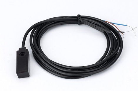
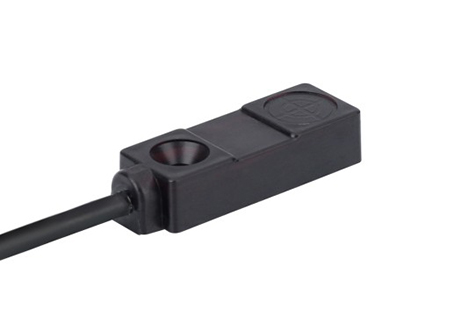
In modern industrial automation, equipment design is moving toward higher density, faster operation, and smarter integration. As a result, traditional bulky sensing solutions are gradually being replaced by compact sensor structures, especially angle post type proximity switches.

These compact designs are not just a trend—they are becoming an industry standard across manufacturing, logistics, robotics, and packaging systems.

Increasing Demand for Space-Saving Designs

Modern machines are no longer spacious or simple. Instead, they are:

More compact

Highly integrated

Packed with multiple sensors and actuators

Why compact sensors matter:

Angle post type sensors allow installation in tight or obstructed areas where traditional straight sensors cannot fit. This makes them ideal for:

Miniature automation equipment

Dense control panels

Multi-axis mechanical systems

As machine design shrinks, sensor design must shrink with it.

Better Adaptation to Complex Machine Structures

Industrial equipment is becoming more customized and less standardized.

Challenge:

Traditional sensors often require:

Straight-line alignment

Large mounting clearance

Simplified installation surfaces

Solution:

Angle post type sensors provide:

Flexible sensing direction

Easier integration into irregular structures

Reduced need for additional mounting hardware

This adaptability is a key reason they are widely adopted in OEM and custom machinery.

Improved Installation Efficiency

Time is critical in industrial production and maintenance.

Advantages of compact sensor structures:

Faster installation in confined spaces

Fewer mechanical adjustments required

Reduced dependency on custom brackets

This directly lowers installation labor costs and speeds up production line setup.

Enhanced Mechanical Protection and Reliability

Compact sensor structures often reduce exposure to mechanical stress.

Why this matters:

In automated environments, sensors are frequently exposed to:

Vibration

Moving machine parts

Accidental impacts

Angle post designs position the sensing head away from direct collision zones, improving durability and reducing failure rates.

Improved Wiring and System Integration

As automation systems become more complex, cable management is increasingly important.

Benefits of compact designs:

More organized cable routing

Reduced cable bending stress

Easier integration into control systems

Cleaner wiring not only improves reliability but also simplifies maintenance and troubleshooting.

Higher Performance in High-Speed Automation

Industries like packaging, sorting, and robotics require fast and accurate detection.

Why compact sensors perform better:

Stable sensing alignment in dynamic motion

Reduced signal fluctuation caused by vibration

Better positioning flexibility for fast-moving targets

This ensures consistent detection even in high-speed production environments.

Industry Shift Toward Standardization of Compact Components

The broader trend in industrial design includes:

Miniaturization of components

Modular machine architecture

Smart factory integration

Compact sensors like angle post types align perfectly with these trends, making them a natural choice for modern systems.

Cost Efficiency Over the Entire Lifecycle

While compact sensors may sometimes seem more specialized, they often reduce total system cost.

Cost-saving factors:

Lower installation time

Reduced mechanical modifications

Fewer replacement issues due to better protection

Less downtime in maintenance

Over time, these advantages significantly improve ROI.

Conclusion

Compact sensor structures like angle post type proximity switches are becoming industry standard because they solve real challenges in modern automation:

Limited installation space

Complex machine geometry

High-speed operation requirements

Demand for reliability and efficiency

As industrial systems continue to evolve toward smarter and more compact designs, these sensors will play an increasingly critical role in ensuring performance, flexibility, and long-term stability.

FAQ 

1. What is a compact sensor structure in industrial automation?

A compact sensor structure refers to a sensor designed with a reduced footprint and optimized shape—such as angle post type proximity switches—that allows installation in tight or complex machine spaces without sacrificing performance.

2. Why are angle post type sensors considered more advanced?

They offer:

Flexible sensing direction

Space-saving installation

Better protection against mechanical impact

Easier integration into modern machine designs

These features align with current automation trends.

3. What industries commonly use compact sensor structures?

They are widely used in:

Automotive manufacturing

Packaging and logistics systems

Robotics and assembly lines

CNC machinery and industrial automation equipment

4. How do compact sensors improve machine design?

They allow engineers to:

Reduce machine size

Simplify mechanical layout

Increase sensor density in limited spaces

Improve overall system integration

5. Are compact sensors more reliable than traditional sensors?

In many applications, yes. Their design often provides:

Better vibration resistance

Reduced exposure to mechanical damage

Improved wiring stability
However, reliability still depends on proper installation and environment selection.

Common Installation Mistakes of Angle Post Type Proximity Switches and How to Avoid Them

Introduction

Angle post type proximity switches are widely used in compact machinery and complex automation systems due to their flexible sensing direction and space-saving design. However, even high-quality sensors can perform poorly if installed incorrectly.

Incorrect Alignment with the Target Object

The problem:

One of the most frequent mistakes is improper alignment between the sensing face and the target object. Because angle post sensors rely on directional detection, even a slight misalignment can cause missed signals or unstable output.

How to avoid it:

Ensure the sensing surface is directly facing the target path

Adjust the angle carefully before tightening the mount

Perform a test run before final locking

Installing Too Close or Too Far from the Target

The problem:

Every proximity switch has a defined sensing distance. Installing the sensor outside this range leads to false triggering or no detection at all.

How to avoid it:

Refer to the rated sensing distance in the datasheet

Keep a safety margin (do not use maximum range as working distance)

Conduct real-world testing under operating conditions

Poor Cable Routing and Electrical Noise Interference

The problem:

Improper wiring layout can cause signal instability due to electromagnetic interference from motors, inverters, or power cables.

How to avoid it:

Separate signal cables from power lines

Use shielded cables when necessary

Ensure proper grounding of the system

Avoid sharp bends or cable tension near the sensor

Weak Mechanical Mounting

The problem:

Loose installation can cause vibration, leading to misalignment or false triggering, especially in high-speed machinery.

How to avoid it:

Use proper torque when tightening mounting nuts

Apply anti-vibration washers or brackets

Periodically check mounting stability during maintenance

Ignoring Environmental Conditions

The problem:

Installing sensors without considering oil, dust, moisture, or temperature can significantly reduce lifespan and performance.

How to avoid it:

Select sensors with appropriate IP rating (IP67 or IP68 for harsh environments)

Avoid direct exposure to coolant spray or chemical splashes

Use protective covers in extreme conditions

Wrong Sensor Type Selection

The problem:

Using an inductive sensor for non-metal targets or choosing an unsuitable detection range leads to poor performance regardless of installation quality.

How to avoid it:

Match sensor type to application (inductive, capacitive, etc.)

Confirm material compatibility before installation

Consult technical specifications before purchase

Overlooking Metal Surroundings and Interference

The problem:

Metal brackets or nearby machine parts can distort the sensing field, causing inaccurate detection.

How to avoid it:

Maintain recommended clearance around the sensing area

Avoid mounting near large metal surfaces when not required

Use shielding or reposition the sensor if interference occurs

Skipping Post-Installation Testing

The problem:

Failing to test after installation may allow hidden issues to go unnoticed until system failure occurs.

How to avoid it:

Perform functional testing under real operating conditions

Check signal stability during machine movement

Simulate long-term operation before full production use

Best Practice Checklist

To ensure reliable performance, always confirm:

Correct alignment with target object

Proper sensing distance

Stable mechanical mounting

Clean electrical wiring layout

Suitable environmental protection level

Correct sensor type selection

Full system testing after installation

Conclusion

Most issues with angle post type proximity switches are not caused by the product itself, but by installation errors. By paying attention to alignment, environment, wiring, and mounting stability, you can significantly improve detection accuracy and system reliability.

Proper installation not only extends sensor lifespan but also reduces downtime and maintenance costs in industrial automation systems.

FAQ

1. What is the most common installation mistake?

The most common mistake is incorrect alignment between the sensing face and the target object. Even small angular deviations can lead to missed detection or unstable signals.

2. How important is sensing distance during installation?

It is critical. Installing the sensor too close or too far from the target can cause:

No detection

False triggering

Unstable output signals

Always follow the manufacturer’s rated sensing distance.

3. Why does electrical noise affect proximity switch performance?

Industrial environments often include motors, inverters, and high-power cables that generate electromagnetic interference. This noise can disrupt sensor signals if wiring is not properly shielded or grounded.

4. Can poor mounting affect sensor accuracy?

Yes. Loose or unstable mounting can cause vibration, leading to:

Misalignment over time

False triggering

Reduced detection reliability

5. Do environmental conditions matter during installation?

Absolutely. Dust, oil, moisture, and extreme temperatures can reduce sensor performance or lifespan. Always choose the correct IP-rated sensor for the environment.