
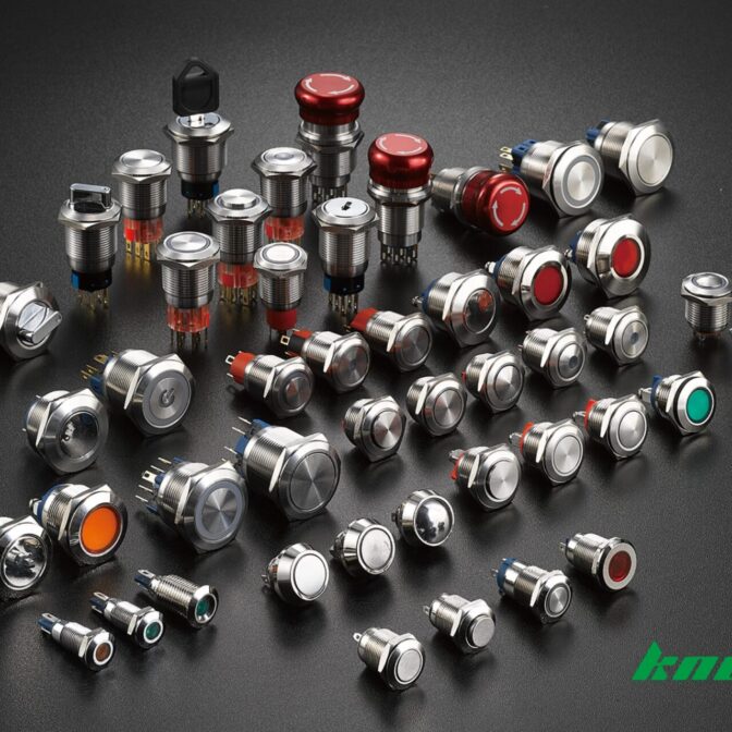
2 Pin Button Switch vs 4 Pin Button Switch: Key Difference

Introduction

In electrical circuit control, choosing the right switch can make or break your design. Engineers and procurement specialists ask one common question: What’s the difference between a 2-pin button switch and a 4-pin button switch? This guide provides a comprehensive comparison of their structure, function, and applications, answering your search intent quickly and clearly. Whether you’re designing for a compact PCB or selecting components for an industrial control panel, this blog helps you choose the right push button for your needs.

Understanding 2-Pin Push Button Switches

2.1 Structure

A 2-pin button switch (also known as a two-pin switch or 2-pin push button) is the simplest form of a tactile switch. It contains just two terminals: one for input and one for output. These terminals are connected by an internal contact mechanism that closes the circuit when pressed. This momentary switch operation ensures that current flows only while the button is held down.

2.2 2 Pin Push Button Working

2 Pin Push Button Working Wiring Diagram

Source:viox

The switch remains open (OFF) by default. When actuated, it momentarily completes the circuit between its two terminals. The internal contact configuration allows current to pass through, enabling the connected load (e.g., an LED or small motor). Once released, the spring-loaded plunger returns the switch to the OFF state. This simple behavior makes it ideal for basic circuit control.

2.3 Application of 2 Pin Push Button

The 2-pin button switch is commonly used in:

  • DIY electronics projects and Arduino boards
  • Home appliances like doorbells and timers
  • Basic signal input for toys and gadgets
  • Compact control circuits with limited space

Its compact design and ease of wiring make it a go-to option for straightforward applications.

Understanding 4-Pin Push Button Switches

3.1 Structure

A 4-pin button switch (often labeled as a 4-pin push button or push button 4 pins) features four terminals arranged in pairs. These terminals are internally connected in two groups, often diagonally. In many cases, one pair is for electrical contact switching, and the other pair powers an LED illuminated switch. The configuration provides more stability during PCB mounting and additional functionality.

3.2 4 Pin Push Button Working

4 Pin Button Switch Working Wiring Diagram

Source:viox

There are two types of terminal configurations for 4-pin button switches:

  1. Dual-contact: Two sets of terminals switch simultaneously, providing dual-path control.
  2. Switch + LED: One pair operates the contact mechanism; the other powers an LED indicator.

During switch actuation, both internal mechanisms are engaged. In LED versions, these lights up the switch, providing visual feedback, making them useful in low-light environments.

3.3 Application of 4 Pin Push Button

These switches are preferred in:

  • Industrial machinery panels and automation systems
  • Microcontroller-based designs (e.g., Raspberry Pi, ESP32)
  • Interfaces requiring visual feedback or status indication
  • Applications demanding enhanced PCB mounting stability and reliability

The additional terminals offer flexibility, making the 4-pin button switch a better fit for more complex electrical designs.

4.1 Number of Terminals

The most obvious difference is the number of terminals. A 2-pin push button includes only one pair of contacts. In contrast, a 4-pin push button consists of two sets of terminals, either wired in parallel for redundancy or separately for LED and switch functions.

4.2 Internal Contact Configuration

In a 2 pin button switch, the internal contact mechanism is straightforward. When pressed, a metal dome bridges the two terminals. However, in a 4-pin button switch, two internal domes or a shared actuator control multiple pathways. In tactile switch variants, this enhances sensitivity and responsiveness.

Some 4-pin types may follow the toggle switch 4-pin configuration, where one set of pins latches after actuation. More often, 4-pole push button switches support complex control requirements such as changeover contacts or redundant safety loops.

4.3 Functionality

While both are designed for momentary switch operation, the 4-pin type adds an extra layer of capability:

  • 2-pin push button: Simple ON/OFF control
  • 4-button switch: Dual control paths or status indication via LED

The push button 4 pines is therefore better suited for circuits needing feedback, redundancy, or multi-circuit activation.

4.4 Wiring Method

Wiring a 2-pin button switch is simple: one wire in, one wire out. It doesn’t require PIN identification. On the other hand, 4-pin push button wiring depends on the internal configuration. Designers must identify which terminals are for switching and which are for the LED.

Typical wiring involves:

  • Using a multimeter to locate the normally open (NO) pins
  • Connecting one pair to the load
  • Powering the LED from the remaining terminals (usually marked with + and -)

This method aligns with IEC standards for switches, especially in professional and industrial environments.

4.5 Typical Industry Scenarios

Here is a breakdown of where each switch type is typically used:

  • Consumer Devices: Both 2 pin and 4 pin button switches are applicable.
  • Industrial Automation: Generally favors 4 pin button switches for their stability and LED feedback.
  • LED Indicator Panels: 4 pin push buttons are preferred due to built-in illumination support.
  • Arduino DIY Projects: Both switches are commonly used depending on project complexity.
  • Machine Tools: Require 4 pin button switches for dual-path or indicator functions.
  • Wearable Tech: 2 pin button switches are more suitable due to size constraints and simplicity.

This comparison shows that push button 2 pines is better for minimal circuits, while 4 pin push button fits more robust and responsive systems.

4.6 Extension Possibility

2 pin switches are limited in terms of scalability. Adding visual cues or safety redundancies requires extra components.

4 pin button switches, especially the LED illuminated switch types, allow extended functionalities like:

  • Visual feedback for user interaction
  • Signal isolation in complex systems
  • Use with PCB mounting switch layouts for increased design flexibility

Moreover, the 4 pole push button switch designs can even handle higher loads or multiple outputs, expanding their use in advanced control systems.

Conclusion

Knd push button switch

To summarize, the 2 pin button switch offers simplicity and ease of use, perfect for basic electrical control. In contrast, the 4 pin button switch delivers enhanced functionality, better stability, and greater flexibility for complex systems.

For professional engineers and technical procurement managers, selecting the right push button means balancing cost, space, and functional demands. Whether you’re designing a tactile switch interface or upgrading an industrial panel, understanding these differences ensures your project stays on track.

Choose a 2 pin push button when you need a compact and cost-effective solution. Opt for a 4 pin push button if your project requires extra feedback, visual indicators, or improved mechanical reliability.
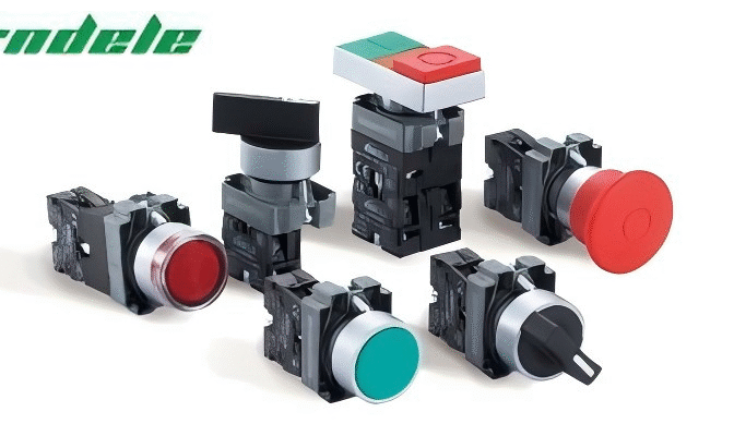
NO vs NC Push Button Switch Comparison: Key Differences

1. What Is a Normally Open Push Button Switch

A Normally Open (NO) switch is a control device that remains open until pressed. In its normal state, the circuit is open, and no current flows. When the button is pressed, the contacts close, allowing current to pass.

This type of switch is commonly used for momentary control actions. It activates a circuit only while it is being pressed. Once released, it returns to the open state, and the current stops.

The normally open switch is often found in applications like start buttons, test triggers, or systems that require manual activation. It’s a simple push-button switch used to temporarily close a circuit.

In control systems, a NO push button helps trigger relays or control signals. It’s often wired into PLC input logic or simple relay-based circuits where momentary action is preferred.

2. What Is a Normally Closed Push Button Switch

KND Electric Flat Head Push Button Switch 1NC

A normally closed (NC) switch works oppositely. In its normal state, the switch keeps the circuit closed. When the button is pressed, the contacts open, and the circuit is interrupted.

This type of switch is designed to break the current when triggered. It is widely used in safety and emergency systems where stopping power is essential. For example, in emergency stop setups, the NC switch push button ensures that the power is cut off immediately when the push button is pressed.

The normally closed configuration is also found in systems like normally closed float switches, limit switches, and microswitches. These switches are ideal for monitoring and controlling fail-safe functions in industrial environments.

When installed in a push button switch panel, the NC version helps maintain constant operation until a stop command is given. It’s essential in any system that requires immediate shutdown when a circuit is broken.

3. NO vs NC Push Button Switch Working Principles

Working Principles Of NO And NC Push Button Switches With Internal Contact DiagramThe main difference between an N.O. and N.C. push-button switch is in their default contact state and how they react when pressed.
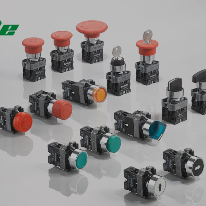
A normally open switch remains open until pressed. It only allows current to flow when activated. This creates a momentary connection in the circuit.

A normally closed switch remains closed until it is pressed. It breaks the current when the button is pushed. This action is commonly used to interrupt control power or shut down machinery.

Both types of switches use an internal contact block that is actuated by a switch actuator mechanism. The button press moves the actuator, which changes the state of the contacts—either opening or closing them based on the type.

In a typical control circuit, NO and NC switches are wired to relay triggers, safety controls, or start/stop functions. Their behavior is predictable and essential for push-button switch types in industrial environments.

4. Application of NO and NC Push Button Switch

NO and NC push button switches are used in a wide range of industrial applications. They are selected based on how a circuit should respond to a user action.

NO push button switches are used for:

  • Motor or machine start commands

  • Temporary testing signals

  • Light activation in operator panels

NC push button switches are used for:

  • Emergency stop buttons

  • Door interlock systems

  • High-risk shutdown controls

In many systems, both types are combined. This is known as an NC NO push button switch, where a single unit provides both NO and NC contacts for flexibility in wiring.

These switches are also found in:

  • Float switch, normally closed systems.

  • Normally closed limit switches

  • Normally open button lighting controls.

Understanding the difference between NO and NC switch configurations helps ensure the correct behavior of machines and systems under both normal and emergency conditions.

5. Security and Functionality Differences

5.1 Fail-Safe Design with NC Switches

Normally closed (NC) pushbutton switches are preferred in fail-safe designs. As the circuit is normally closed by default, any wire cut, power failure, or actuator fault results in an open circuit. This stops the system immediately, providing built-in protection.

That’s why normally closed push switch designs are common in emergency stop circuits and interlock systems.

5.2 Control Logic Impact of NO Switches

In PLC input logic, NO push buttons are useful for triggering momentary actions. They provide a pulse input to start a motor or set a relay.

Normally open(NO) switches are not used for stop functions, since they don’t break the circuit by default. However, they are ideal for signaling “start” or “go” tasks in automation systems.

5.3 Safety Standards Compliance

Both switch types must comply with standards like IEC 60947-5-1, IEC 60204-1, which govern safety ratings, color codes, and wiring behavior. For example, NC switches used in e-stops often include red actuators and yellow backgrounds for immediate identification.

These standards also define circuit behavior during power loss and require proper labeling of normally open vs normally closed contact points.

5.4 Reliability Considerations

In critical environments, reliability is tied to both electrical and mechanical properties. NC switches are often used in systems where downtime is not acceptable. Their ability to fail safely makes them more reliable for safety-critical roles.

NO switches, while reliable, rely on being pressed to complete a circuit, which may not suit all applications.

6. Mechanical and Structural Differences

6.1 Internal Components Overview

Both NO and NC switches share similar mechanical housing, but the internal contact block and spring mechanism vary. The difference between NO vs NC switch types is driven by how the actuator moves the internal contacts.

6.2 Contact Materials and Durability

Contact materials affect how long a switch lasts. Silver alloy is common, but gold-plated contacts are used in low-voltage circuits. High-load systems need contacts with arc resistance.

Durability is especially important in normally closed microswitch or enclosed switch designs used in continuous operation.

6.3 Housing and Sealing Ratings (IP)

Industrial push button switches are rated for IP65/IP67 enclosure ratings. This defines their resistance to dust and water. Enclosures with higher ratings are preferred in wet or dusty environments.

Switch housing and sealing protect internal components from corrosion and mechanical damage, especially for outdoor panels or factory floors.

6.4 Mechanical Life and Wear

Both switches are rated in mechanical life cycles, often over one million actuations. NC switches in high-cycle systems may wear faster due to constant load.

Proper material selection and actuator design extend the service life and improve push button switch reliability over time.

7. Normally Open vs Normally Closed Switches – Selection Factors

7.1 Environmental Considerations

For wet, dusty, or corrosive settings, switches with enclosure ratings like IP65 or IP67 are necessary. Enclosed switch designs help maintain reliability in tough environments.

7.2 Electrical Load Requirements

Different switches support different load types. For low-voltage signals, gold contacts in an NC switch push button may be needed. For high power, make sure the contact rating matches your current and voltage.

7.3 Application-Specific Needs

Use NO push buttons for initiating events. Use NC push buttons for stopping or fail-safe features. In critical machines, both are used together as an NC NO-push-button switch.

7.4 Maintenance and Troubleshooting

NC switches are easier to diagnose in open-failure scenarios. A failed NC contact will usually break the circuit, stopping the machine. With NO switches, a failed wire might go unnoticed.

Proper labeling and testing using continuity checks help reduce downtime.

7.5 Cost and Availability

Push button switches come in a wide range of prices. Standard NO or NC types are affordable. Custom NO/NC combo switches or sealed units cost more but offer more flexibility.

8. Conclusion

The difference between NO and NC switches is essential knowledge for anyone working in control systems or industrial automation. NO switches allow power to flow only when pressed, while NC switches stop the current when triggered. Each has a clear function depending on your safety, logic, or operational requirements.

Understanding the roles of normally open and normally closed switches helps prevent wiring errors, improve system design, and ensure safety compliance.

When choosing components for your next project, always consider load, environment, and application logic before making a decision. If you’re looking for durable, compliant, and reliable push button switches, KND Electric offers a wide range of products designed for industrial-grade performance.

9. FAQs About NO and NC Push Button Switches

Q1: What happens if I use an NC switch where NO is needed?
The circuit will behave in reverse. It may stay energized by default and disconnect when pressed, opposite of what’s expected.

Q2: Can a push button switch have both NO and NC contacts?
Yes. Many industrial switches are designed as NC no push button switch units, combining both functions in a single device.

Q3: How can I test if a switch is NO or NC?
Use a multimeter in continuity mode. For NO, it shows open until pressed. For NC, it shows closed until pressed.

Q4: Which is safer in emergency systems—NO or NC?
NC push button switches are preferred for emergency stops. They open the circuit when pressed and fail safely if wiring is damaged.

Momentary Push Button Switch vs. Latching Push Button Switch

1. Introduction

Push button switches are fundamental components in industrial electrical control systems. Whether it’s turning on machinery, initiating an emergency stop, or controlling lighting systems, these switches offer reliable human-machine interaction.

At their core, push button switches serve a critical function: they open or close an electrical circuit when manually actuated, enabling control over devices, equipment, and entire systems.

Within the wide world of push button switches, two common types dominate control panel designs and OEM applications: the momentary push button switch and the latching push button switch. While they might look similar on the outside, their internal behavior and control functions are significantly different.

This article will walk you through their definitions, operating principles, comparative features, and practical advice on how to choose the right switch for your project or purchase needs.

2. What Is a Momentary Push Button Switch?

2.1 Definition

A momentary push button switch is a type of switch that only maintains its circuit status while being pressed. Once pressure is released, it automatically returns to its original position and state—open or closed depending on the design.

You likely interact with momentary push buttons every day—think elevator buttons, doorbells, or machine start/stop controls.

2.2 Working Principle

The momentary push button switch contains a spring-loaded mechanism. When you press the button, the contacts close (or open in normally closed types), completing the circuit. When you let go, the spring pushes the button back, and the contacts return to their original state.

This switch is ideal for tasks where temporary activation is needed—start motors, activate alarms, or trigger a process without needing to maintain contact.

China 22MM Momentary Push Button Switch

3. What Is a Latching Push Button Switch?

3.1 Definition

A latching push button switch, also known as a self-locking or maintained switch, changes its state every time you press it. Press once to turn on, press again to turn off. It “latches” into position until manually reset.

These are common in light switches, control panels, and toggle-type operations where state memory is required without constant finger pressure.

3.2 Working Principle

Internally, latching switches include a mechanical or electrical latching mechanism that locks the switch contacts in place after actuation. This can involve a physical detent or an electronic relay to hold the new position.

Unlike momentary switches, there is no return spring to reset the state. That makes it a better choice for long-term on/off control.

China Latching Push Button Switch
image description

4. Understanding the Differences: Momentary Push Button Switch vs. Latching Push Button Switch

In industrial automation and electrical control systems, choosing the right type of push button switch isn’t just a matter of preference—it can directly affect machine behavior, operator safety, and system efficiency. Let’s explore the key differences between momentary push button switches and latching push button switches across various technical and functional dimensions.

4.1 Behavior

The core behavioral difference lies in how each switch responds after being pressed.

  • A momentary push button only stays engaged while being held. This behavior is often described as spring return—once the pressure is removed, the button returns to its original state automatically. This makes it suitable for controls like an equipment start button, foot switch momentary, or test pulse trigger.

  • A latching push button maintains its new state after actuation. One press closes the circuit, and the next opens it. It’s like a toggle switch but in button form, often with a mechanical locking mechanism that holds its state until it’s pressed again.

This difference is crucial when deciding how you want your device or system to behave during and after interaction.

4.2 Mechanical Design

From an engineering perspective, the internal mechanics vary significantly:

  • Momentary switches rely on a spring return mechanism, ideal for temporary connections. They’re designed for high-cycle use in repetitive operations. Some models, such as the 2 way momentary switch or switch DPDT momentary, offer dual-directional or double-pole configurations for complex circuits.

  • Latching switches, on the other hand, include an internal mechanical latch or detent system. This structure allows them to hold a state until deliberately reset. These are commonly used in electrical cabinets where the user doesn’t want to hold the switch continuously.

4.3 Circuit Control

  • Momentary switches are often used to send a momentary signal to a relay control or PLC control. This makes them perfect for activating processes without permanent circuit engagement—such as in a machine jog mode, alarm trigger, or manual override.

  • Latching switches offer a maintained signal and are more appropriate when you want something to stay powered until the operator changes it. For example, turning on lights in an industrial control panel, or controlling an automation system that doesn’t need constant human interaction.

4.4 Installation & Maintenance

Installation is generally straightforward for both types. Most fit standard panel cutouts and support both surface-mount and flush-mount formats. However, consider the following:

  • Momentary buttons tend to be more common in emergency stop button applications. Their frequent use and safety-critical roles mean they must be highly durable and often require IP65 or higher protection.

  • Latching switches require attention to mechanical wear of the locking mechanism. They’re often found in power panels or equipment master control points, where access is more restricted, and actuation frequency is lower.

Routine inspection and function testing are especially important for both types when deployed in automation equipment or safety-critical scenarios.

4.5 Durability

Durability often correlates with the switching cycle count:

  • High-quality momentary switches can withstand millions of cycles, especially when built with industrial-grade materials like stainless steel or anodized aluminum. They’re ideal for repetitive-use cases like foot pedal controls, production line stations, or manual process triggers.

  • Latching switches, while robust, tend to have slightly lower actuation life due to more moving parts in the latch mechanism. However, modern designs have significantly improved in longevity and vibration resistance.

4.6 Cost

From a procurement standpoint:

  • Momentary push button switches are generally more cost-effective, especially in simple rocker switch momentary or basic push-to-make models.

  • Latching buttons, with their more complex internal mechanisms, are slightly more expensive, particularly if they include features like LED illumination, dual-contact outputs, or modular relay interface compatibility.

Cost should be evaluated alongside lifecycle expectations, as higher-quality switches reduce long-term maintenance costs.

4.7 Switching Mode

This refers to how the circuit is controlled and how current flows:

  • Momentary switches support non-latching switching: current flows only when the button is depressed.

  • Latching switches support maintained switching, where the state persists independently of physical pressure. This is critical in applications like mode selection, reset control, or manual bypass functions in a control system.

4.8 Advantages

Momentary Push Button Switch:

  • Fast, responsive control

  • Ideal for temporary actions

  • Safer for emergency functions

  • Simpler and lower cost

Latching Push Button Switch:

  • Enables hands-free operation

  • Maintains ON/OFF state without constant user input

  • Excellent for long-term power toggling

  • Adds memory-like functionality in basic systems without PLCs

4.9 Electrical Specifications

Both types are available in a range of ratings:

  • Voltage: Typically from 12V DC to 250V AC

  • Current: Commonly from 3A to 16A

  • Contact types: SPST, SPDT, DPDT (e.g., switch DPDT momentary)

  • Terminals: Solder lug, screw, or quick-connect

  • Compliance: UL, CE, RoHS for safety and reliability

Engineers should match switch specs with system requirements like load type, inrush current, insulation resistance, and short-circuit tolerance.

4.10 Safety Features and Compliance

In industrial settings, switches must meet safety compliance:

  • Momentary buttons used in safety switch applications often include:

    • Fail-safe mechanisms

    • IP67 waterproof designs

    • Panel lockout features

  • Latching switches require reliable locking action to prevent unintended toggling, particularly when used in high-vibration environments.

Both types should conform to international standards for operation in regulated industries such as manufacturing, energy, or transport.

5. Application of Momentary Push Button Switch and Latching Push Button Switch

Momentary Switch Applications:

  • Machine start/stop buttons

  • Alarm systems

  • Test benches

  • Signal triggering in PLCs

  • Emergency stop controls

Latching Switch Applications:

  • Power control switches

  • Light switching

  • Industrial process toggles

  • Reset functions

  • HVAC panel control

Understanding these use cases helps engineers and procurement professionals determine which switch aligns with their system requirements.

6. How to Choose Between Momentary and Latching Push Button Switch

Choosing the right switch isn’t just about form factor—it’s about function, environment, and user expectations. Here are some critical considerations:

6.1 Application Requirements

Ask: Does the switch need to maintain its state after being pressed? If yes, go for latching. If not, momentary fits.

6.2 User Interaction

Momentary switches require continuous pressure, suitable for brief interactions. Latching switches are preferred for one-time activation with long effect.

6.3 Environmental Factors

If your device operates in wet or dusty environments, IP-rated metal push buttons are essential—available in both momentary and latching versions.

6.4 Electrical Load Characteristics

Momentary switches work well with control signals. For power switching, latching models with higher amperage ratings may be better suited.

6.5 Installation and Maintenance

Consider switch lifespan, number of cycles, mounting options, and panel space. KND switches, for instance, offer durable metal bodies and compact designs optimized for modern control panels.

7. Conclusion

Both momentary push button switches and latching push button switches play vital roles in electrical control systems. Understanding their operating principles, strengths, and applications allows engineers and purchasing managers to make informed decisions, ensuring safety, efficiency, and longevity in industrial settings.

Looking for high-quality, durable momentary push button switches that meet global safety standards and industrial-grade performance?

👉 KND Momentary Push Button Switches

Our switches are engineered for excellence, with IP-rated protection, rugged metal bodies, and customizable contact configurations to suit a wide range of industrial applications.